

What Is a WAAM Compact System and How Does It Work?
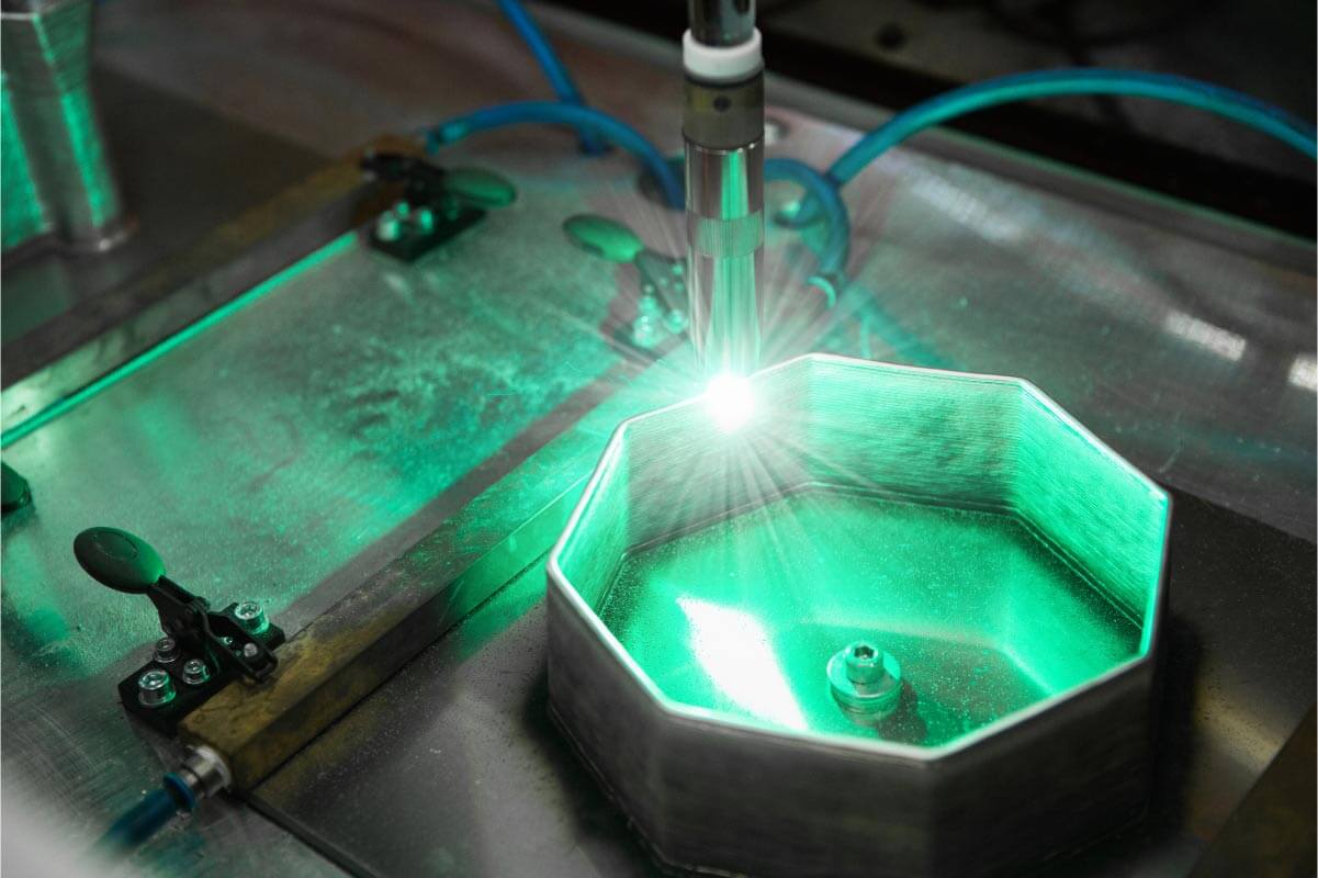
Deploying Wire Arc Additive Manufacturing in an industrial facility involves more than mounting a welding torch on a robot. The robot, power source, positioner, process software, safety equipment, sensors, lighting, monitoring devices, and material-handling provisions must operate as one coordinated production system.
A WAAM Compact System integrates these elements within a dedicated robotic cell designed for metal additive manufacturing. Instead of engineering every subsystem separately, manufacturers receive a compact, plug-and-play platform in which the principal deposition, motion, control, safety, and monitoring technologies are combined.
MetalWorm Compact Systems are developed specifically for robotic Wire Arc Additive Manufacturing. They enable manufacturers to build near-net-shape metal components by depositing continuously fed metallic wire layer by layer using an arc-based heat source.
The Compact System range includes different robot and positioner configurations for varying component dimensions, payloads, axis requirements, and production workflows. Lodestar 3D provides MetalWorm WAAM solutions in India and supports manufacturers in selecting a system appropriate for their material, geometry, production, and process-control requirements.
[Internal Link: MetalWorm Compact System Product Page]
Table of Contents
What Is a WAAM Compact System?
A WAAM Compact System is an integrated robotic manufacturing cell that uses the Wire Arc Additive Manufacturing process to produce metal components.
The system normally combines:
- An industrial robot
- A wire-based deposition torch
- An arc power source
- A component positioner
- Offline programming software
- Process diagnostic tools
- Safety equipment
- Torch-cleaning equipment
- Cell lighting
- CCTV or process observation equipment
- Temperature and process sensors
- Optional advanced monitoring technologies
The purpose of integration is to reduce the complexity of establishing an industrial WAAM operation.
In a conventional integration project, the manufacturer may need to procure a robot, select a welding source, design the cell, install safety barriers, develop toolpaths, integrate sensors, create a control interface, and validate communication between the different systems.
A compact robotic cell brings these technologies together within one controlled production environment.
This does not eliminate the need for application engineering. Engineers must still select suitable materials, develop process parameters, plan deposition paths, manage heat, define machining allowances, and validate the finished component. However, an integrated cell provides the technological foundation on which that process can be developed.
How Does a WAAM Compact System Work?
A WAAM Compact System converts a digital component design into a near-net-shape metal part through coordinated robotic deposition.
The production workflow can be divided into several stages.
1. The component is designed digitally
The process begins with a three-dimensional CAD model.
Engineers assess whether the component is technically and commercially suitable for WAAM. Strong candidates often include large metal parts that would otherwise require extensive machining, fabrication, casting tooling, or multi-part assembly.
The design may be modified to account for:
- Deposition direction
- Layer height
- Bead width
- Robot accessibility
- Positioner movement
- Thermal distortion
- Machining allowance
- Support or fixture requirements
- Start and stop locations
- Part orientation
The final CAD geometry is converted into deposition paths using offline programming or additive manufacturing software.
2. The deposition path is programmed
The robot needs more information than the external shape of the part. It requires a controlled path that defines how each layer will be deposited.
The programming stage establishes:
- Robot trajectory
- Torch orientation
- Travel speed
- Layer sequence
- Positioner movement
- Wire feed rate
- Deposition start and stop commands
- Interpass waiting periods
- Process parameter changes
MetalWorm Offline Programme is available in both the Standard and Advanced system configurations.
Offline programming allows engineers to prepare and evaluate robot paths digitally rather than teaching the entire component manually inside the cell. This can reduce programming effort and improve repeatability for complex or multi-axis builds.
3. Metal wire is continuously supplied
Wire Arc Additive Manufacturing uses metallic wire as the feedstock.
During production, the wire is fed continuously toward the deposition zone. Depending on the selected power source and material, the system can work with an appropriate MIG, MAG, TIG, plasma, or laser-based configuration.
Only one power-source type is selected for a particular system configuration.
The material must be compatible with the deposition process and the performance requirements of the finished component. Depending on application development and process qualification, WAAM may be used with weldable materials such as steels, stainless steels, aluminium alloys, titanium alloys, nickel-based alloys, and other engineering metals.
4. The heat source melts the wire
The selected energy source melts the incoming wire and creates a controlled molten pool.
In arc-based configurations, electrical parameters and wire-feed behaviour determine how the material is transferred into the melt pool.
Important process variables include:
- Current
- Voltage
- Wire feed speed
- Robot travel speed
- Gas flow
- Torch angle
- Contact-tip distance
- Layer height
- Interpass temperature
The interaction of these parameters determines bead width, bead height, penetration, deposition stability, thermal input, and surface condition.
5. The robot deposits each layer
The industrial robot moves the deposition torch along the programmed trajectory.
As the wire melts, material is deposited onto a substrate or onto the previously completed layer. The molten bead cools and bonds metallurgically with the material below it.
The sequence is repeated:
- Wire enters the deposition zone.
- The energy source melts the wire.
- The robot follows the programmed path.
- A metal bead is deposited.
- The layer solidifies.
- The robot or positioner changes orientation.
- The next layer is added.
This controlled repetition creates a three-dimensional near-net-shape component.
6. The positioner controls part orientation
The positioner is a critical part of the Compact System.
A six-axis robot provides substantial movement freedom, but the positioner adds external axes that allow the workpiece to rotate or tilt. This helps keep the deposition torch at a suitable angle and gives the robot access to different surfaces.
Depending on the model, MetalWorm Compact Systems can include:
- A two-axis positioner
- A two-station rotary positioner
- A Double Skyhook positioner
- A THDZ positioner
The combined robot and positioner axes influence the types of geometries that can be produced.
Multi-axis movement can also help engineers avoid limiting every component to simple vertical wall deposition. The workpiece can be repositioned to support more controlled deposition on curved, angled, or otherwise difficult-to-access surfaces.
7. The process is monitored during operation
WAAM involves repeated heating, melting, deposition, and cooling. Process conditions can therefore change as the component grows.
MetalWorm Compact Systems are designed to control and monitor production events during operation. The available level of monitoring depends on whether the Standard or Advanced configuration is selected.
Process monitoring may involve data such as:
- Temperature
- Torch-to-part distance
- Gas flow
- Humidity
- Oxygen level
- Bead or layer appearance
- Welding current and voltage
- Sound signatures
- Thermal behaviour
- Three-dimensional surface condition
This information can help operators detect deviations before they affect a substantial portion of the build.
8. The near-net-shape part is finished
A WAAM Compact System normally creates a near-net-shape component rather than a fully finished precision part.
The deposited geometry may therefore require:
- CNC machining
- Heat treatment
- Stress relief
- Surface finishing
- Dimensional inspection
- Non-destructive testing
- Mechanical testing
- Metallurgical evaluation
Machining allowance should be included during design and toolpath planning. Critical interfaces, holes, sealing faces, bearing surfaces, and tight-tolerance features are commonly completed after deposition.
Core Components of a WAAM Compact System
The effectiveness of the system depends on how its individual technologies work together.
Industrial robot
The robot controls the deposition torch and follows the programmed build path.
MetalWorm systems may be integrated with ABB, KUKA, or FANUC robots. The robot brand and model can change depending on the sector, required working envelope, payload, application, and integration needs.
The specified configurations currently include ABB robot models, but buyers should confirm the final robot configuration during technical consultation.
Positioner
The positioner holds and moves the component during deposition.
Its purpose is not limited to supporting part weight. It also creates additional motion axes and helps maintain favourable deposition orientation.
Positioner selection affects:
- Component accessibility
- Build orientation
- Maximum payload
- Part dimensions
- Number of stations
- Deposition flexibility
Power source
The power source generates the energy required to melt the wire.
MetalWorm lists MIG, MAG, TIG, plasma, and laser among the available power-source categories, depending on system configuration. The MHTTN500DS specification specifically identifies MIG, MAG, and TIG.
The correct source depends on material, deposition rate, heat-input requirements, process stability, surface quality, and research or production objectives.
Software and diagnostics
Both Standard and Advanced systems include:
- MetalWorm Offline Programme
- MetalWorm Diagnostic
The Advanced configuration adds:
- MetalWorm Machine Vision
- MetalWorm Control
- MetalWorm Anomaly Detection
This advanced software layer is relevant for manufacturers that need more process visibility, automated supervision, and data-supported production control.
Sensors
A pyrometer is available in both Standard and Advanced configurations.
The Advanced configuration can include or optionally support a wider sensor set, including:
- Laser distance sensor
- In-cell humidity sensor
- In-cell temperature sensor
- In-cell oxygen sensor
- Gas flow meter
- SWIR thermal welding camera
- HDR welding camera
- Infrared thermal camera
- Microphone
- 3D camera
- Spectrometer
- Interferometric sensor
- Profilometer
- Welding current and voltage sensor
Not every application requires every sensor. The correct configuration should be based on the process risks, material, validation requirements, and quality strategy.
Safety and cell equipment
Both system levels include:
- Torch cleaning
- In-cell lighting
- Industrial safety equipment
- CCTV
These elements are important because WAAM combines robotic movement, electrical energy, hot metal, arc radiation, shielding gas, and automated production.
Standard vs Advanced MetalWorm Compact Systems
MetalWorm Compact Systems are available in Standard and Advanced configurations.
Standard configuration
The Standard configuration provides the fundamental technologies needed for robotic additive manufacturing.
It includes:
- Selected power source
- Torch-cleaning system
- In-cell lighting
- Industrial safety equipment
- CCTV
- MetalWorm Offline Programme
- MetalWorm Diagnostic
- Pyrometer
This configuration may be appropriate for manufacturers that have a defined application, established quality methods, and do not require a broad range of in-cell sensing or automated anomaly-detection capabilities.
Advanced configuration
The Advanced configuration extends the system through machine vision, process control, anomaly detection, and additional sensors.
It includes the Standard capabilities plus:
- MetalWorm Machine Vision
- MetalWorm Control
- MetalWorm Anomaly Detection
- Laser distance sensing
- Humidity monitoring
- Cell-temperature monitoring
- Gas-flow measurement
- SWIR thermal welding camera
- Microphone-based monitoring
Additional technologies are available as options, including oxygen sensing, HDR welding cameras, infrared thermal cameras, 3D cameras, spectrometers, profilometers, interferometric sensors, and welding current and voltage sensing.
The Advanced version is relevant when manufacturers require deeper process monitoring, more production data, closed-loop control potential, or stronger foundations for Industry 4.0 integration.
Optional Equipment and Add-On Technologies
Both Standard and Advanced systems can be configured with operational options such as:
- Gas filter
- Fixture or clamp
- Crane for removing the manufactured part
- Trolley for transferring the manufactured part
MetalWorm also lists the following add-on technologies:
- Active cooling
- In-situ heating
- Vibration technology
Active cooling
Active cooling can help manage heat accumulation between layers. This may support more stable interpass temperature and reduce waiting periods, depending on the material and process strategy.
In-situ heating
Controlled heating may be useful for materials or geometries that require thermal management before or during deposition.
Vibration technology
Vibration may be evaluated as part of process development where engineers are studying bead behaviour, solidification, residual stress, or metallurgical outcomes.
These technologies should be selected through application-specific testing rather than added without a defined process objective.
Applications of a WAAM Compact System
A WAAM Compact System can support production, development, tooling, and repair applications in sectors such as:
Aerospace
- Structural components
- Near-net-shape titanium or aluminium parts
- Tooling
- Repair development
- Low-volume metal components
Automotive
- Prototype metal components
- Forming tools
- Jigs and fixtures
- Motorsport parts
- EV development components
Defense
- Replacement parts
- Vehicle and naval components
- Repair of high-value assets
- Localised metal component production
- Large functional prototypes
Industrial engineering
- Custom machinery components
- Large metal structures
- Tooling inserts
- Heavy fixtures
- Near-net-shape replacement parts
Foundry and casting
- Molds and tooling
- Pattern-related metal structures
- Repair of worn tooling
- Low-volume components without dedicated casting tooling
- Hybrid additive and machining workflows
Research and education
For research applications that require a smaller or more flexible experimental platform, MetalWorm also offers a dedicated Lab System. Compact Systems are better positioned for integrated industrial-cell deployment and controlled manufacturing workflows.
[Internal Link: WAAM Applications Case Study]
How to Select the Right WAAM Compact System
The choice should begin with the component and production requirement, not with the model name.
Manufacturers should evaluate:
- Maximum component dimensions
- Total part and fixture weight
- Required number of external axes
- Need for single- or two-station operation
- Material and power-source compatibility
- Robot reach and payload
- Thermal-management requirements
- Sensor and quality-monitoring needs
- Loading and unloading method
- Machining and post-processing workflow
- Production volume
- Data-traceability requirements
The MHTTN1000 may be preferred when a higher positioner payload is essential. The MHTTN500RP may suit a two-station rotary workflow and rectangular component envelope. The MHTTN500DS offers the highest listed number of external axes, while the MHTTN500THDZ provides an intermediate three-axis positioner configuration.
When none of the listed systems matches the application, MetalWorm can develop a custom system.
Building an Industrial WAAM Capability with Lodestar 3D
A WAAM Compact System provides an integrated route into robotic metal additive manufacturing. It combines deposition equipment, robotic motion, workpiece positioning, offline programming, diagnostics, safety systems, and optional advanced process monitoring within one cell.
The four MetalWorm configurations address different payloads, component sizes, axis requirements, and station arrangements:
- MHTTN1000 for a 1,000 kg two-axis positioner workflow
- MHTTN500RP for two-station rotary operation
- MHTTN500DS for complex motion using a Double Skyhook
- MHTTN500THDZ for a three-axis, two-station positioner configuration
Choosing between these systems requires a clear understanding of component geometry, material, deposition process, thermal behaviour, productivity goals, quality requirements, and downstream machining.
Lodestar 3D supports Indian manufacturers in evaluating MetalWorm WAAM technology as part of a complete additive manufacturing strategy. Its technical team can assist with system selection, application assessment, equipment integration, process planning, service, and support.
Consult Lodestar 3D to determine which WAAM Compact System is appropriate for your component dimensions, production environment, material, and industrial application.
[Internal Link: Contact Lodestar 3D for a Quote]
FAQ's
1. What is a WAAM Compact System?
A WAAM Compact System is an integrated robotic cell that produces metal components by depositing continuously fed wire layer by layer. It combines an industrial robot, power source, positioner, software, sensors, and safety equipment within one manufacturing cell.
2. Is a WAAM Compact System the same as a metal powder 3D printer?
No. A WAAM system uses metallic wire and an arc or another selected energy source. Metal powder bed systems use a layer of powder selectively melted by a laser or electron beam. WAAM is generally selected for comparatively large, near-net-shape metal components.
3. What is the maximum part size of a MetalWorm Compact System?
The listed maximum component envelope depends on the model. The MHTTN1000, MHTTN500DS, and MHTTN500THDZ list a maximum size of Ø0.7 × 0.7 metres. The MHTTN500RP lists 1 × 0.5 × 0.7 metres.
4. What is the difference between Standard and Advanced systems?
Both configurations include the main power-source options, torch cleaning, lighting, industrial safety equipment, CCTV, offline programming, diagnostics, and a pyrometer. The Advanced system adds machine vision, control, anomaly detection, and a broader range of available sensors.
5. Do parts produced in a WAAM Compact System require machining?
Most WAAM parts require some post-processing because the process produces near-net-shape components. CNC machining, heat treatment, stress relief, inspection, and surface finishing may be required to achieve the final tolerance and performance specifications.