

What Is a Robotic WAAM System and How Does It Work?
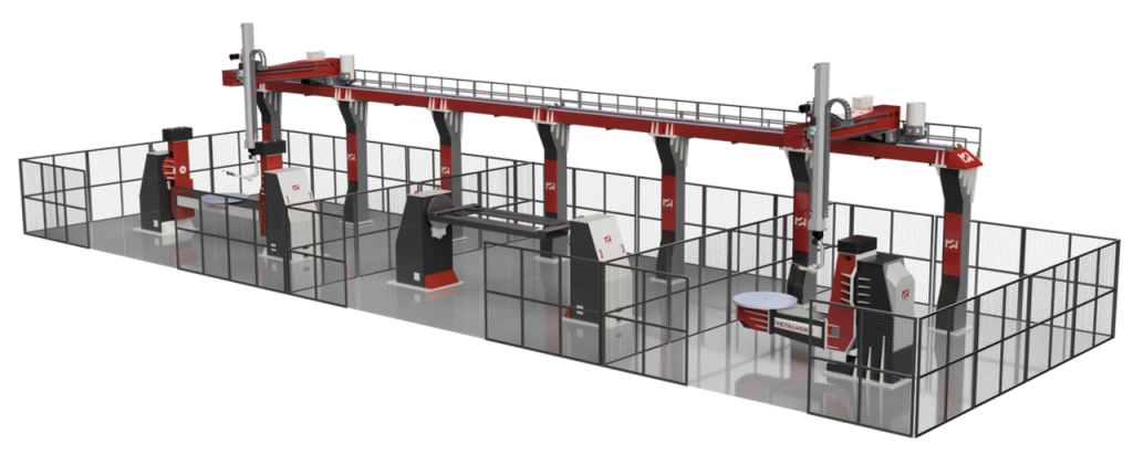
Producing a large metal component through additive manufacturing requires more than a deposition torch. The system must control where material is placed, how the workpiece is positioned, how heat accumulates, and how each deposited layer compares with the digital design.
A Robotic WAAM System brings these functions together by combining Wire Arc Additive Manufacturing with industrial robotics, workpiece positioners, software, sensors, and process-control technologies.
Table of Contents
WAAM stands for Wire Arc Additive Manufacturing. It is a wire-fed metal additive manufacturing process in which a controlled heat source melts metallic wire and deposits it layer by layer. The deposited metal solidifies and bonds with the previous layer, gradually forming a near-net-shape component.
The industrial robot controls the deposition path. A positioner may rotate or tilt the workpiece, while software coordinates the robot, power source, wire feeder, and monitoring devices.
This architecture makes robotic WAAM particularly relevant for medium and large metal parts, tooling, repair, feature addition, and low-volume industrial production.
Lodestar 3D provides MetalWorm robotic WAAM solutions in India for different manufacturing and research requirements.
What Is a Robotic WAAM System?
A Robotic WAAM System is an automated metal additive manufacturing platform built around an industrial robot.
The robot carries the deposition torch and follows a programmed three-dimensional toolpath. Metal wire is continuously fed into the deposition zone, where it is melted by an arc or another selected energy source.
The principal elements of a robotic WAAM environment can include:
- Six-axis industrial robot
- Wire-feeding mechanism
- Deposition torch
- Welding or energy source
- Workpiece positioner
- Build substrate
- Shielding-gas system
- Offline programming software
- Process-control software
- Cameras and monitoring sensors
- Safety enclosure and interlocks
- Thermal-management technologies
These elements operate as one coordinated system.
The robot controls torch movement, but it does not work independently. Wire-feed speed, heat input, shielding gas, travel speed, layer height, torch distance, and workpiece orientation must all remain within suitable process limits.
How Does a Robotic WAAM System Work?
The robotic WAAM workflow begins with a digital model and ends with a deposited metal component ready for machining, finishing, and inspection.
1. Component Design and Application Assessment
The process begins with a CAD model.
Before programming the robot, engineers assess whether the part is suitable for WAAM. Strong candidates are often medium or large components that involve:
- High material waste during machining
- Expensive casting or forging tooling
- Low production quantities
- Long procurement lead times
- Complex welded assemblies
- Repairable high-value structures
- Large near-net-shape volumes
The design may be modified for additive manufacturing. Engineers evaluate build direction, accessibility, bead geometry, thermal behaviour, machining allowance, and fixture requirements.
WAAM is not chosen only because a part can be printed. It should provide a measurable advantage in cost, lead time, material use, design, repair, or supply-chain resilience.
2. Slicing and Robotic Toolpath Creation
The digital component is divided into layers and converted into robotic deposition paths.
The toolpath tells the robot:
- Where to begin deposition
- Which direction to travel
- How fast to move
- How each bead should overlap
- When to start and stop wire deposition
- How the torch should be oriented
- When the workpiece should rotate
- How each new layer should be approached
Offline programming enables engineers to prepare the robot path digitally rather than manually teaching every movement inside the cell.
The software must account for more than geometry. Robot-axis limits, singularities, collisions, cable routing, torch access, positioner movement, and process timing must also be considered.

3. Wire Feeding and Arc Generation
Metal wire is supplied continuously to the deposition torch.
Depending on the chosen process and application, robotic WAAM may use technologies based on:
- MIG or MAG welding
- TIG welding
- Plasma arc welding
- Other wire-based directed energy processes
In an arc-based process, electrical energy creates intense heat between the electrode or torch and the workpiece. This heat forms a molten pool.
The wire enters the deposition zone and melts into the pool.
Shielding gas protects the molten material from harmful atmospheric interaction. The selection of wire, shielding gas, and deposition process depends on the alloy, mechanical requirements, productivity target, and intended application.
Lorem ipsum dolor sit amet, consectetur adipiscing elit. Ut elit tellus, luctus nec ullamcorper mattis, pulvinar dapibus leo.
- Lorem ipsum
- Lorem ipsum
- Lorem ipsum
- Lorem ipsum
Lorem ipsum dolor sit amet, consectetur adipiscing elit. Ut elit tellus, luctus nec ullamcorper
4. Layer-by-Layer Metal Deposition
Once the molten pool is established, the robot moves the torch along the programmed path.
The operating sequence is straightforward:
- Wire is fed into the deposition zone.
- The heat source melts the wire.
- The robot moves along the planned trajectory.
- Molten metal forms a controlled bead.
- The bead solidifies and bonds with the material below it.
- The robot moves to the next path or layer.
- Deposition continues until the component is complete.
Each deposited layer becomes the foundation for the next one.
The robot must therefore maintain consistent travel speed, torch angle, path position, and distance from the workpiece. Variations can affect bead dimensions, layer height, surface condition, heat input, and the final geometry.
5. Robot and Positioner Synchronization
A six-axis robot provides substantial movement freedom, but some geometries require additional workpiece movement.
A robotic positioner can rotate, tilt, or reorient the part while the robot moves the torch. The robot and positioner operate as synchronized axes within the same toolpath.
This coordination can help:
- Maintain a favourable deposition orientation
- Improve access to curved surfaces
- Produce cylindrical components
- Control the influence of gravity on the melt pool
- Reduce difficult robot postures
- Reach different sides of a large component
- Support complex multi-axis deposition
For larger components, the system may also include a linear slider, vertical axis, or gantry. These peripherals extend the robot’s normal working envelope.
6. Heat and Interpass Temperature Control
WAAM introduces repeated heating and cooling cycles into the component.
As the part grows, heat can accumulate. Excessive thermal buildup may influence:
- Bead shape
- Layer height
- Microstructure
- Residual stress
- Distortion
- Surface quality
- Mechanical performance
The system may pause between layers until the component reaches a defined interpass temperature.
Advanced control can also adjust travel speed, wire-feed rate, cooling, or heat input based on measured process conditions.
Optional technologies such as active cooling and in-situ heating may be used where the material or application requires a more controlled thermal strategy.
7. Process Monitoring and Sensor Feedback
Industrial robotic WAAM can incorporate sensors to observe the production process while deposition is taking place.
Available monitoring technologies may include:
- Pyrometers
- Thermal welding cameras
- HDR welding cameras
- 3D cameras
- Laser distance sensors
- Profilometers
- Current and voltage sensors
- Gas-flow sensors
- Temperature and humidity sensors
- Oxygen sensors
- Microphones
- Spectrometers
The collected data can be associated with robot coordinates and timestamps. This helps engineers determine where a process deviation occurred within the component.
Monitoring can identify changes related to temperature, gas flow, torch distance, bead formation, electrical stability, or environmental conditions.
This creates a traceable digital manufacturing record rather than relying only on final inspection.
8. Real-Time Geometry Correction
A programmed toolpath assumes that each layer will be deposited at the expected height and shape. Actual deposition may vary because of heat, material behaviour, bead overlap, or process fluctuations.
Advanced robotic WAAM systems can measure the deposited layer and modify the following path.
For example, the system may:
- Measure the completed layer using a 3D camera
- Compare actual geometry with the target
- Detect changes in layer height
- Adjust the robot’s vertical position
- Modify the next toolpath
- Maintain the required torch-to-part distance
- Pause until the correct temperature is reached
This closed-loop approach can improve dimensional consistency and process stability.
9. Post-Processing and Inspection
Robotic WAAM normally produces a near-net-shape component.
The printed part is close to its required geometry but usually needs additional manufacturing operations.
Post-processing may include:
- CNC machining
- Heat treatment
- Stress relief
- Surface finishing
- Dimensional inspection
- Non-destructive testing
- Mechanical testing
- Metallurgical evaluation
Critical holes, threads, mating faces, bearing locations, sealing surfaces, and other precision features are commonly finished through machining.
Post-processing requirements should be considered during design. Engineers must include sufficient machining allowance without depositing unnecessary material.
Types of MetalWorm Robotic WAAM Systems
MetalWorm provides three principal system categories for different operating requirements.
Compact Systems
Compact Systems combine the principal robotic WAAM technologies in an integrated cell.
They are suited to manufacturers seeking a controlled, factory-ready production environment for compatible component sizes and workflows.
Special Systems
Special Systems are developed for larger, heavier, longer, or more complex parts.
They may incorporate heavy-duty positioners, sliders, gantries, multiple robots, tables, or several production stations.
The system architecture can be configured around the part and manufacturing requirement.
Lab Systems
Lab Systems are designed for academic research, industrial R&D, material testing, and process development.
They allow researchers to investigate different wires, deposition parameters, sensors, thermal strategies, robotic paths, and control methods.
Applications of Robotic WAAM Systems
Robotic WAAM can support several manufacturing strategies.
New-part production
The system can manufacture large near-net-shape components such as frames, housings, flanges, structural preforms, rings, and custom machinery parts.
Tooling, molds, and dies
WAAM can build the main volume of forming tools, molds, dies, welding fixtures, and assembly tooling before precision machining.
Repair and remanufacturing
Material can be deposited onto worn or damaged regions of an existing component. The restored area is then machined and inspected.
Feature addition
Ribs, bosses, flanges, supports, or connection features can be added to an existing plate, forging, casting, or preform.
Functional prototypes
Engineering teams can manufacture large metal prototypes for testing, assembly validation, product development, and design improvement.
Industries That Can Use Robotic WAAM
Relevant sectors include:
- Aerospace and space
- Defense
- Automotive and mobility
- Marine and shipbuilding
- Energy and power generation
- Oil and gas
- Industrial engineering
- Foundry and casting
- Rail and heavy transportation
- Research and education
The strongest opportunities are generally found where components are large, costly to machine, produced in limited volumes, difficult to source, or associated with high tooling investment.
Benefits of a Robotic WAAM System
A properly selected and engineered system can provide:
- High deposition rates for large metal volumes
- Reduced material waste
- Lower dependence on molds and dies
- Greater flexibility for customized parts
- Multi-axis manufacturing capability
- Consistent robotic motion
- Repair and remanufacturing capability
- Digital production traceability
- Reduced assembly through part consolidation
- Localized manufacturing of selected components
These benefits depend on application selection and process development. WAAM is not automatically more economical for every metal part.
Limitations to Consider
WAAM also has practical limitations.
It may not be the best process for components requiring:
- Very small features
- Fine internal channels
- High as-built surface quality
- Tight tolerances without machining
- Very thin unsupported geometry
- Extremely high-volume production
- Materials unsuitable for wire deposition
The process also requires thermal control, skilled programming, machining, inspection, and application-specific qualification.
Metal Powder Bed Fusion may be better for compact and intricate parts, while casting, forging, or machining may remain more economical for other production scenarios.
Conclusion
A Robotic WAAM System enables efficient production of large, complex metal components through controlled wire deposition, robotic motion, and process monitoring. It is well suited for manufacturing, tooling, repair, and low-volume industrial applications where material efficiency and design flexibility are important.
FAQ's
Is robotic WAAM the same as robotic welding?
The technologies are related, but their objectives differ. Robotic welding joins existing components. Robotic WAAM uses controlled welding-based deposition to build or modify a component layer by layer.
Why are industrial robots used in WAAM?
Industrial robots provide programmable multi-axis motion, controlled torch orientation, repeatability, and integration with positioners, sensors, and process software.
Can robotic WAAM produce large parts?
Yes. Robots can work with sliders, gantries, rotary axes, and heavy-duty positioners to manufacture components beyond the limits of many enclosed metal additive systems.
Do robotic WAAM parts require machining?
Most WAAM components require CNC machining or another finishing process to achieve final tolerances and surface requirements.
Can a robotic WAAM system repair an existing part?
Yes. The system can add material to selected worn or damaged regions. The repaired component must then be machined, inspected, and validated.